|
Hill Railway , Blisworth, Northamptonshire, UK. All pictures are presented at relatively low resolution.
There will be hundreds of pictures on this site - there is an economic limit to the
webspace available. The point of this presentation is that you
can see for yourself the extent of the collection and return
later as the collection expands - as it surely will. Any interest in copies of a picture
at a higher resolution (ie. clarity) should be directed
through contacts given in the Blisworth "Round and About"
parish council publication. In some cases the pictures are not available due to copyright restrictions.
However, permission has been obtained, where
possible, to include them here. Printed below each image is the
photographer's name, if known.
|
||
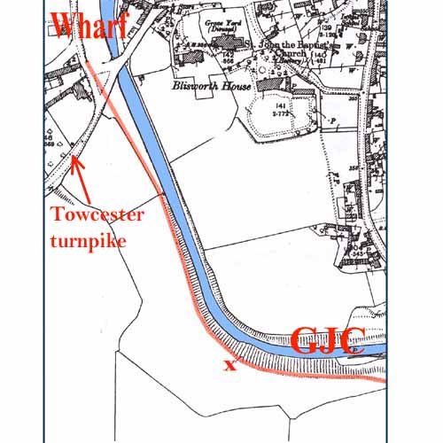 |
35-00 The map shows the southwestern edge of Blisworth with the Grand Junction Canal (GJC) passing under West Bridge. The north portal of the tunnel is a quarter mile to the south. At a time when both stretches of the canal were completed between Birmingham and London, with only the Blisworth Tunnel to finish, Benjamin Outram was contracted to build a tramway (as we now call it) which joined the two halves over Blisworth Hill. The tramway was in service for five years between 1800 and 1805. Outram had already built tramways elsewhere in England and this one appears to be of a very similar design. Wooden wagons with cast iron wheels and axles were drawn by teams of horses - steam engines which were mobile (ie. locomotives) were only just being invented by Trevithick at about the time. The red line shows the path that the tramway, or perhaps more appropriately the plateway, took running south from Pickford's wharf at Blisworth. It was originally laid from a point to the south of the turnpike bridge but was extended to the larger wharf area to the north a few months later. Generally the path was made up of hardcore over a width of about 6 yards and two sets of "rails" were place side by side. In the area covered by this map there seems to be a profile which could accommodate only one set of "rails" and in the region indicated by the "X" even a single width seems challenged by the eroding embankment against the canal. This fact seems to suggest earth movements after the plateway was taken up and a possible reason is offered at the end of the article on this website dealing with the tunnel construction. The line of the plateway over
the hill covers a distance of well over three miles in a series of reasonably
straight sections. It extended as far as Stoke Bruerne bottom
lock. See map for its position
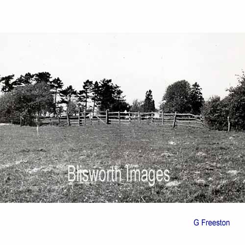
shown by a pink line. 35-01 This c. 1965 picture shows a field boundary on Tunnel Hill Farm which crossed the band of hardcore bedding for the plateway. The hedge never thrived on the hardcore and so a gap is left. |
|
 |
||
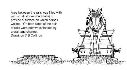 |
This drawing by Brian Collings illustrates
the twin path of the plateway. The need for paths and drainage
channels on the outsides explains the wide swathe across the fields required by the plateway. The horse is shown drawing by chains. This method would require a wheel-braking system on the wagons to prevent wagons from running into the horse on a downward incline. A common brake design was based on a metal 'slipper' placed in front of wheels to cause skids. Brian has the separation of the two tracks about right - this shot was helpful in confirming it. |
|
|
|
If you click on the small picture to the left a
diagram will be presented which shows how the trackway was constructed.
This |
|
| A Rough Timeline of the
Research Sept 1956 G
Freeston's diary "Stuart Woolacott and I have been digging up
sleeper blocks". 1962 V
Hatley publishes his monograph. May 1963
Letters between V Hatley and GF on further work, revisions for a reprint
and GF's work on the use of plateway components for the limestone rail
and afterwards, perhaps, for the
horse rail link from Blisworth Arm to Northampton. Sept
1964 The departing farmer at Blisworth Hill Fm (Mr
Ridgeway) finds a whole plate embedded in a chimney breast c.1965-70
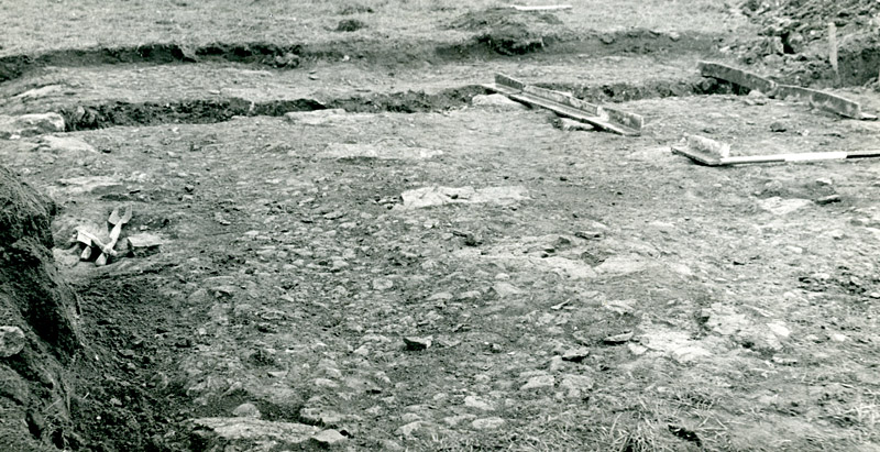
Stimulated by the incoming farmer (Mr Taylor) who began deep ploughing,
there was a substantial effort to excavate as much as possible - with probable
Northampton Archeological Society involvement - which resulted in the
majority of the photographs reproduced here. May
1968
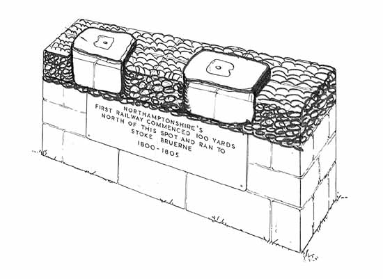
GF attempts to establish a memorial stone tablet for the plateway near
to Grafton House in Blisworth. The caption he prepared read:
1800 - 1805 He receives full approval from the Parish Council and the NCC (with the condition that the parish council maintain it) but nothing happened. There was the view, which was left un-minuted, that there was a lack of funds which were thought better spent on a much needed Village Hall. July 1984 GF contacts the Geological Museum to enquire the source of the sleeper stones - answer probably the "Mill-stone Grit" strata in Derbyshire. 2000 Brian Collings constructs his model of the over-hill plateway and installs it at the Canal Museum along with related exhibits from rail transport elsewhere in the country. 2014 The BHS become excited about a possible display board which may incorporate the history of the ironstone railways as well. |
||
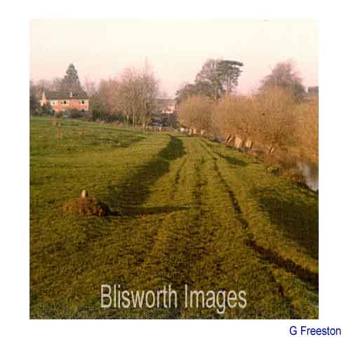 |
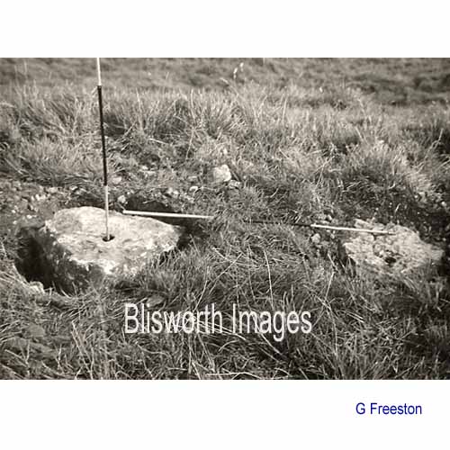
35-00a The profile of the plateway 300 yards south of the Mill still looks much like this today - in this case emphasised in the setting sun. The cast iron marker post indicates the extent of the GJCCo land. The purpose of the very generous leveled "path" outside the GJCCo boundary is not clear. It seems likely that it provides accommodation for one of the two railways and the assignment of landrights to the canal company came later. Photograph taken at Christmas 1976.
|
|
|
Footnote: The evidence of a causeway running across the next but one field, going south, has been substantiated recently in a photograph provided by an engineer from Mowlems. Take a look at the article on our manorial fishpool - the last two pictures on the page, particularly. |
||
 |
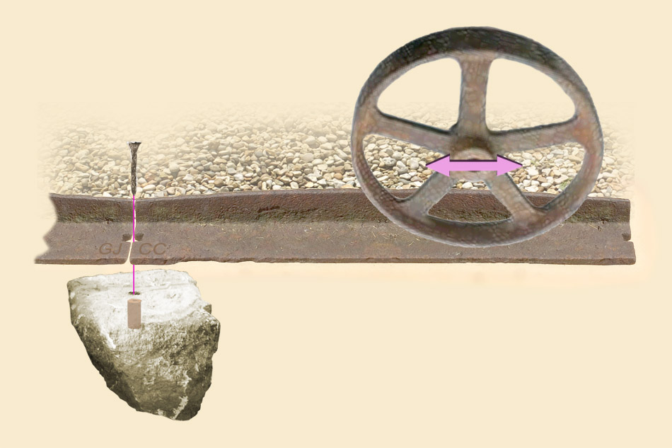
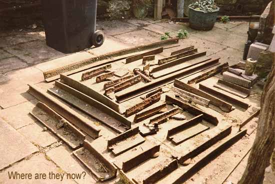
35-02 Each set of "rails" were supported on two rows of limestone sleepers set at 36" intervals. The stone has been analysed and appears to have originated in Derbyshire. | |
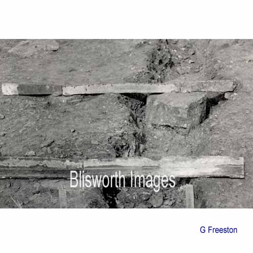 |
35-03 Each "rail"
is basically a row of cast iron plates which bridge between sleeper
blocks which were laid in rows. A railway or "plateway"
consists of two rows separated by a fixed distance to suit the axles of the wagons.
This picture shows a re-construction of a short part of the plateway.
Bridging with cast
iron elements was a weakness in the design and, no doubt, replacements
of the brittle plates were needed virtually continually. Each
plate carried embossed lettering; GJ at one end and CC at the other to
signify the "Grand Junction Canal Company".
The wagon wheels run on the flat surface of the plates while the vertical section of the plates guides the wheels, retaining them on that surface. The vertical section also provides rigidity. |
|
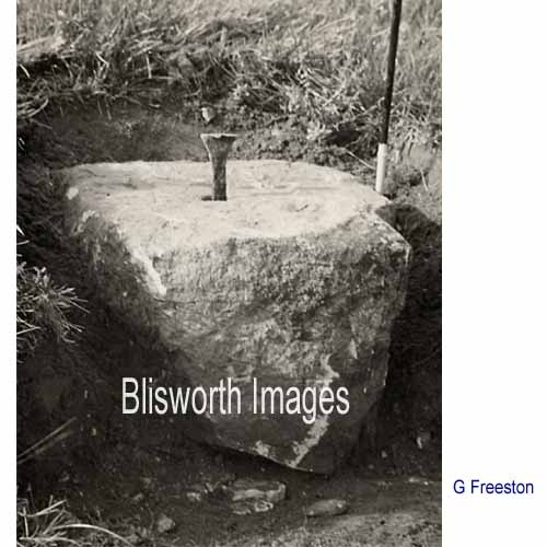 |
35-04 Each sleeper block is drilled with a hole which accommodated a drilled wooden plug and the plates were held in place with a wrought iron spike driven into the plug. | |
 |
35-05 The plates were
butt joined. Their ends were fashioned with a squared indented profile to take
the peg as can be seen in the next picture. The underside of each
plate end was thickened with a "D" shaped boss of cast iron
which would bed into the stone, thus promoting stability. The
design is referred as a foot-mounted plate. The plates were in fact made as a single casting,
including bosses at each end and included the upright section to one
side. This picture more clearly shows the L-shaped cross-section
of the plates. The upright sections were
placed on the inside of the line intended for the wheels and prevented
the wagons from running off the plates. Important advantages of
this design were that the casting process for the plates was simple and
the wagons could be run off the ends of the track and turned and
manipulated on their wheels on the wharf hard-standing. The upright sections were placed on the inside of the wheels so that a bed of gravel could be laid between them for the horses to walk on. The wheels usually possessed a narrow flat tread (see 35-11 below) so that any stones lying in the path of the wheels would be crushed or pushed out of the way. |
|
|
Footnote: If
one returns briefly to picture 35-03, |
||
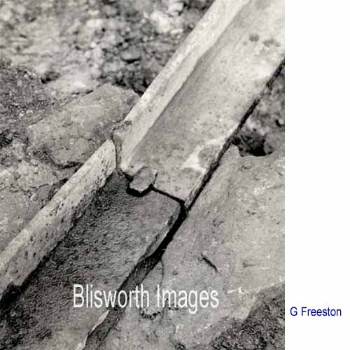 |
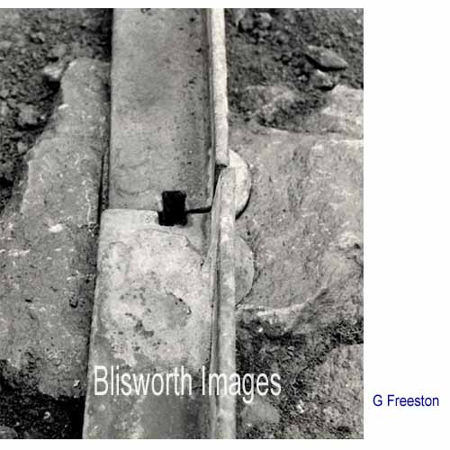
35-06 This shows the peg
in place to provide a smooth joint for the wagon wheels to pass over.
Unfortunately no wheels were found, it seems. If any
were found they disappeared as quickly as did most of the entire plates
evident in these pictures. One entire plate resides in the Stoke Bruerne Museum
in an exhibit created by Brian Collings. Many were grouped for a photograph!
Note the rectangular form of the spike head designed to fit the square indents at the ends of the plates. |
|
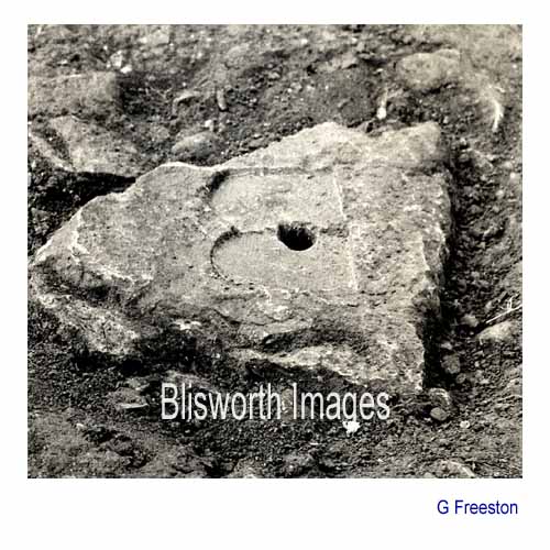 |
35-07 Most of the stones have the imprints of two "D" shaped bosses at the joins of two plates. The combined effect is of a "B" shaped worn hollow centred about the hole for the peg. | |
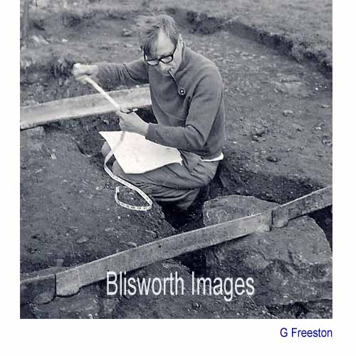 |
35-09 This fellow, whose
identity is unknown at present, appears
to be about to measure the track width, ie. the gauge of the plateway. The Northampton
Archeological Society was involved in the late 1960s work but, according
to Geoffrey Starmer, the notes have been lost and were never written up. Victor Hatley* estimated the gauge
to be 4' 2" which would be consistent with many of Outram's
tramways.
This picture tends to give the wrong impression, in one respect, since the plates appear to have been placed with their upright sections to the outside of the path of the wheels - contrary to the accepted layout. Alternatively, the person is measuring the separation between the 'up' and 'down' tracks. |
|
|
*Footnote: Victor A. Hatley, late Northamptonshire historian, published a monograph in 1962 entitled "The Blisworth Hill Railway 1800-1805" as a reprint from the Reports and Papers of the Northamptonshire Antiquarians Society. This article is still definitive. He remarked then that only one 14" piece of plate had been found. The excavations pictured here were carried out c.1965-68 and clearly have been successful in recovering many more pieces. George Freeston found yet more when it was realised, from the Grafton records of an audit of his agent John Roper, that plates had been donated c.1815 by the Grand Junction Canal Company to the Blisworth Stone Quarry. This was for a plateway running down to a canal wharf near the north portal of the tunnel. Another horse rail line was established between Blisworth Arm and Northampton until completion of the flight of locks 1815 though unlikely that the same components were used. |
||
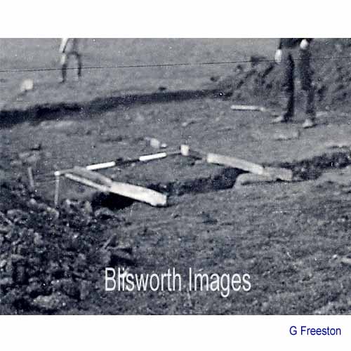 |
35-10 A surveyor's pole marked in 12" sections shows the track width to be at least 4 foot. | |
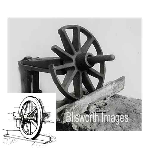 |
35-11 This picture
appears to be a display item of a wheel of diameter of 15" to
18" resting on a similar plate to the Blisworth plates. The
means of holding the plate, ie. the chair, is a good deal more
sophisticated however than the arrangement used on Blisworth Hill.
It was evidently thought by George Freeston that the wagon wheels used
would resemble this one.
The inset drawing by Brian Collings is of a wheel of familiar design but based on flared spokes. There is no evidence available on what actual design was used. |
|
|
A newspaper notice announced the sale of goods at 10am on 14th march 1805 by Mrs Ludham at Stoke Wharf, on the Grand Junction Canal, near Blisworth, in the County of Northampton : These properties have been used on the Rail-Way, and will be sold without Reserve [note: it was not referred to as a tramway] Twenty-Four stout Horses and one Nag, in excellent condition; 24 Sets of very good Harness; one Six-inch and two Narrow-wheel Waggons, very lately new; one stout Timber-carriage; upwards of 300 Load of rich Manure, in six lots; Quantity of Wood; and various other Effects. By 2nd October in the same year there was a sale at Stoke Wharf of all the effects of Mr Joseph Ludham - a Bankrupt. |
||