|
Tunnel Repairs - 1982, Part II , Blisworth, Northamptonshire, UK. All pictures are presented at relatively low resolution. Any interest in copies of a picture at a higher resolution (ie. clarity) should be directed through contacts given in the Blisworth "Round and About" parish council publication or using the comment form on the home page. In some cases the pictures are not available due to copyright restrictions. However, permission has been obtained, where possible, to include them here. Printed below each image is the photographer's name, if known.
|
|
|
Back to Home Page Part I This is Part II |
|
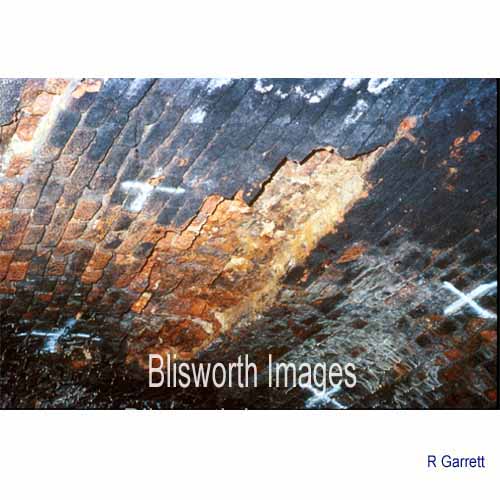 |
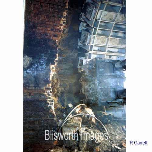
19-13 Not just the central third of the tunnel required attention. There were numerous patches of broken off brickwork eroded by the action of water. |
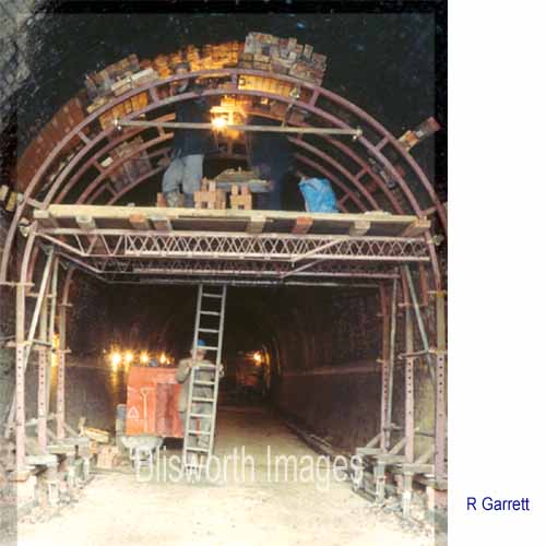 |
19-14 If the roof seemed sound nonetheless, a specially shaped scaffold was erected for the bricklayers to stand on.
|
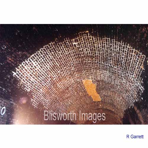 |
19-15 A renewed patch of brickwork. |
 |
19-15a If the roof was thought unsafe then some hoops were jacked into position to support things more thoroughly. |
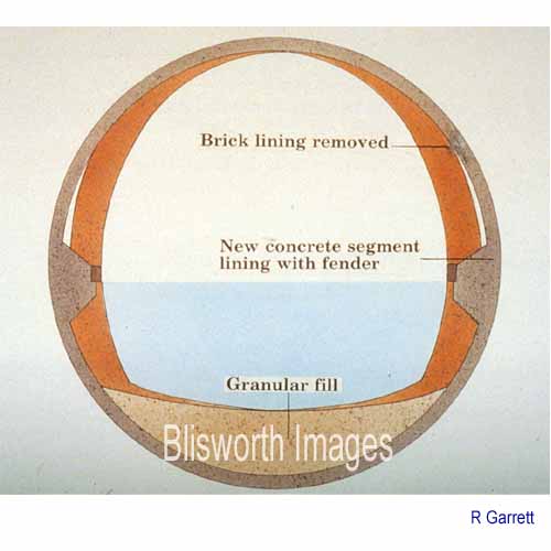 |
19-16 The central third
could obviously not be replaced by old-fashioned labour intensive
brickwork. Concrete pre-formed sections would be erected to form a
perfectly circular tunnel which matched the elliptical form of the
original tunnel. As the new form was so deep, being circular, it
would be simply filled with gravel road material.
Where the concrete was to be fitted, the brickwork would be removed. |
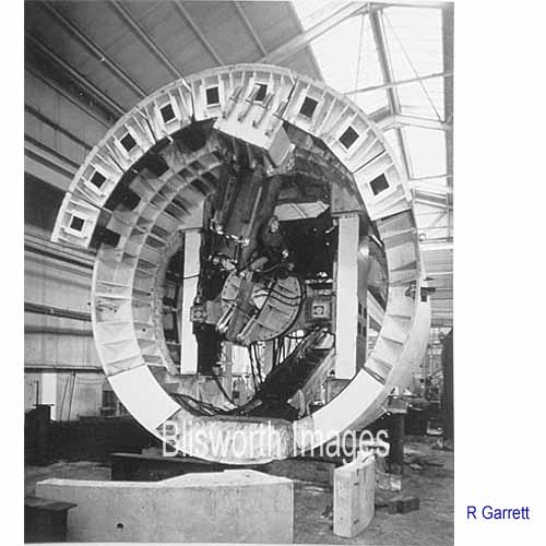 |
19-17 This rather large piece of machinery is known as a tunnelling shield. It has at the near end a digger attachment which will be used to break away the brickwork.
|
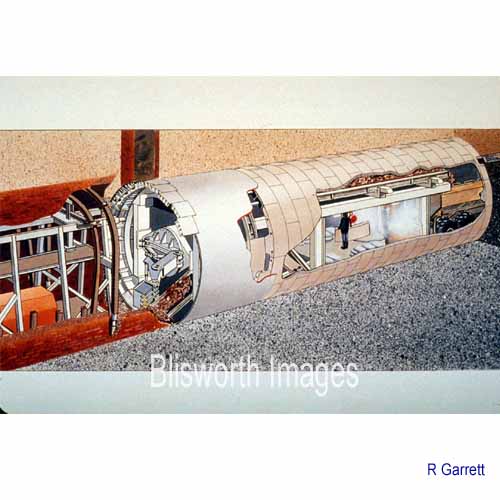 |
19-18 The jacked up hoops
to the left of this schematic support the tunnel as brickwork is nibbled
away. The shield, which of course is assembled in situ, is then
push forward to reach more brickwork. Behind it are placed
interlocking concrete sections. A series of dumper trucks back up
to the end of a conveyor built into the shield and carry away broken
bricks which were poured into a convenient natural
depression in a nearby field which was once a fish pool.
The schematic also shows one of many ventshafts to the top of the tunnel which required special attention, as did the numerous ports for the discharge of water behind the walling. |
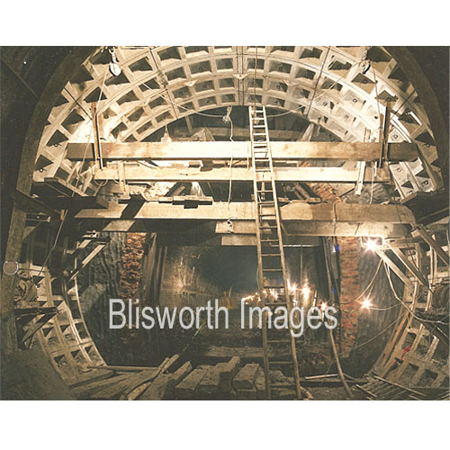 |
The background shows the tunnel walling and the foreground the large circular concrete lined space where the shield is to be assembled. Once the shield is operational it will proceed to cut out more brickwork and push itself forward (pushing against this ring) and insert more rings of concrete. This initial accommodation for the shield had however to be excavated and assembled by hand. |
 |
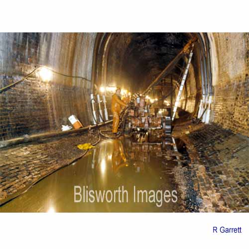
19-19 A picture of the side of the tunnel where brickwork has been nibbled away. A little more should be removed before the shield can again be advanced by hydraulic action. The brickwork should be about 18 inches thick but in some places the builders had cut a few corners. |
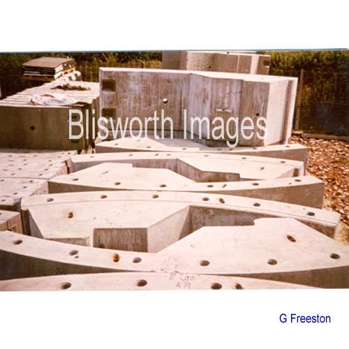 |
19-20 These are the concrete sections which interlock to form a bonded circular tube. A short account on the logistics for supplying these components is included. |
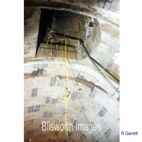 |
19-21 Where there is a
ventshaft (see next picture), the brickwork of the tunnel is cut away as normal. This
leaves the entire column of
brickwork in the vent supported by friction. Concrete is poured to form an
adaptive joint between the vent brickwork and the regular renewed
concrete tube of the tunnel.
This operation required that the position of these shafts were known in
advance, by GPS survey, so that non-standard pieces of concrete section could be
brought in by truck at the right time to be fitted in place.
Two loads of brick rubbish leaving the workface was matched with one load of suitable sections being brought in. |
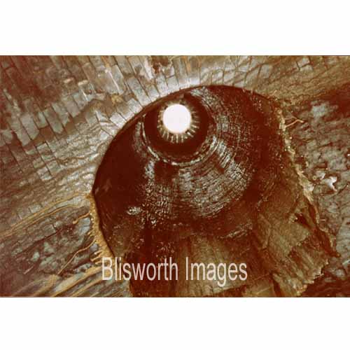 |
19-21a An unusual shot in that the bore of the vent appears dry. This vent is about 24 metres tall - probably the first one going south near Tunnel Hill farm.
|
| 19-22 This picture was taken from a viewpoint in the old elliptical tunnel and shows the start of the circular sections. In the distance there is the shield which, at the end of its work, will be dismantled to allow boats to pass but the cylindrical "skin" of the machine will be left in place to serve in lieu of brick or concrete. | |
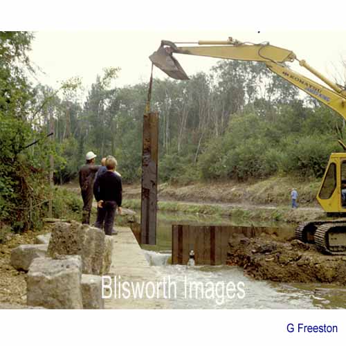 |
19-23 The temporary stank shown in Part I was replaced by steel pilings and here the first one or two are being removed to allow water to fill the tunnel at the end of the works.
|
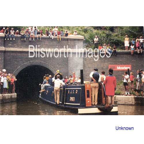 |
19-26 In the Spring of
1984, after a few expressions of impatience by canal users who were
badly inconvenience by the tunnel closure, the dams were taken away and
a celebratory run through the tunnel was enacted. The procession
was led from the north end by a beautifully restored old steam tug Spider on which there
were dignitaries including George Freeston. For an archival
picture of Spider see 08-65 near the bottom end of the Canal
Boats page.
George Freeston, in September 1984, wrote a memoir note on the closing actions in connection with the tunnel repairs. |
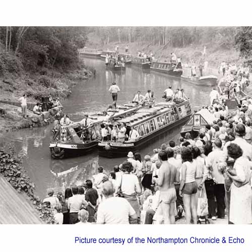 |
19-27 Various boats, watched by a good turn out of villagers, made up the procession. The traffic through the tunnel for the next week was considerable. |
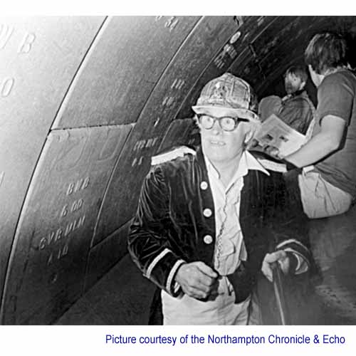 |
19-28 Here is George making a inspection of the tunnel from Spider. |
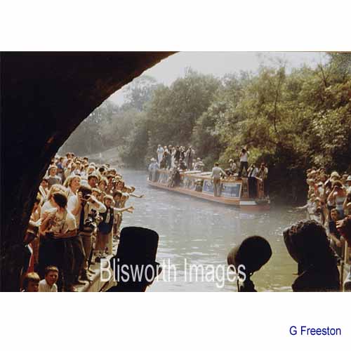 |
19-29 At the other end, Stoke Bruerne, a happy crowd greets the boats. |
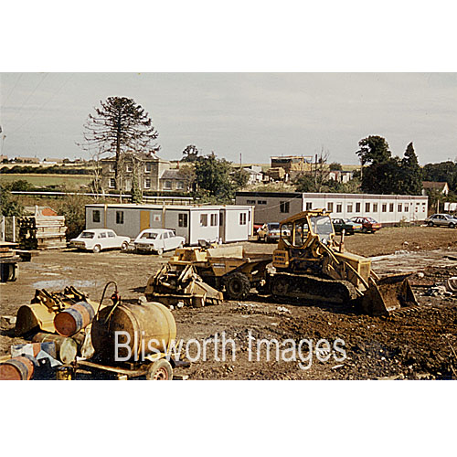 |
Taken during the project - quite a substantial village of machinery and portacabins had sprung up near the Stoneworks farm. |
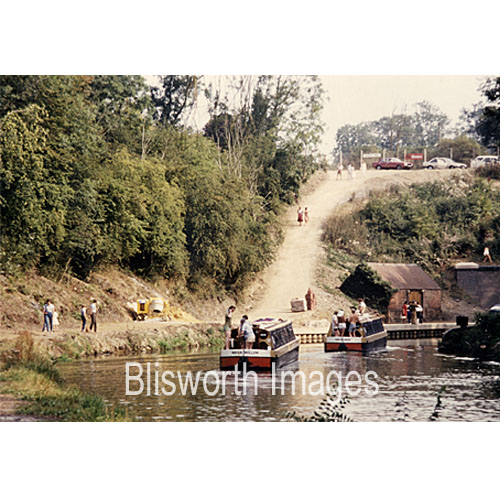 |
The area was sealed off, so no-one saw the use of earth moving machines as the canal- side was restored. This picture shows that the steepness of the land immediately adjacent to the towpath was increased considerably from its original 20 degrees. Later, BW covered much of this raw profile with a layer of subsoil blue clay. For what reason no one has any idea but its effect has been drastic in terms of achieving an overly sterile 'topsoil'. Compare this view with that at the start of the project - image 19-09 in part I.
|
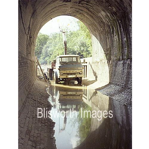 |
Here is a reminder of the massive scale of
the excavation. Compare with the profile in the next picture and
you will see that the water came up to half way up the lorry windscreen
- a deep channel so that water can get past the boats as they move
through the tunnel.
This lorry was one of the last, equipped to pick up junk etc. |
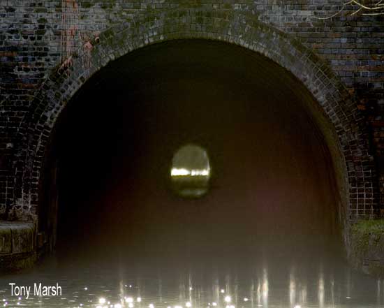 |
The tunnel at 3056 yards long is very nearly
dead straight and much credit must go to the Georgian engineers.
On clear days with low traffic, the other end can be easily seen from
the towpath at the Blisworth end. This is best in winter.
Use of binoculars is advisable. In this photo I have enlarged
the sight of the far end by 10 times to give an impression of a
tunnel only 305 yards long.
The tunnel wall actually "wriggles" by over 1 metre both in and out
and something similar happens to the roof. Consequently the far end can be seen
only over a rather narrow range of positions. To find the right
viewing spot, start by standing on the brick wharf near to the water's edge and work backwards,
away from the tunnel mouth, until you get to the end of the brick wharf.
Now you are in the ideal position. If you move about a little you can see the view being cut off because of the
non-straight sides. Hang on to any kids trying this!! |