|
Tunnel Repairs - 1982, Part I , Blisworth, Northamptonshire, UK. All pictures are presented at relatively low resolution. Any interest in copies of a picture at a higher resolution (ie. clarity) should be directed through contacts given in the Blisworth "Round and About" parish council publication or using the comment form on the home page. In some cases the pictures are not available due to copyright restrictions. However, permission has been obtained, where possible, to include them here. Printed below each image is the photographer's name, if known. |
||
|
Back to Home Page This is Part I Part II |
||
|
||
|
Since the construction of these pages there has been a
celebration, at both Stoke Bruerne and Blisworth, for the There is also a block of 220 slides taken mostly by
George Freeston, mostly of people, |
||
 |
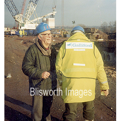
19-00 In the early 1980s it had become clear that major works would be needed in the Blisworth tunnel because of crumbling brick work and a heave upwards of the base of the tunnel in some places which caused concern for heavily laden narrow boats. The tunnel was cut mainly through blue clay, which has given little trouble. However, for the central third of the tunnel, its roof penetrated through the sandy iron-bearing strata which dipped in the centre of Blisworth Hill. The water from this stratum caused progressive blocking of the original header ducts designed to carry away the excess so that water was being forced to lie against the brickwork. This ultimately eroded the joint mortar. Many of these pictures were taken by Robin Garrett who was the chief engineer for British Waterways for the repair work. |
|
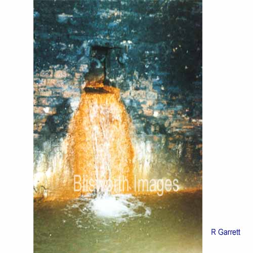 |
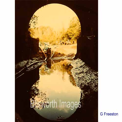
19-01 The tunnel has numerous ports from which water laden with iron continually flowed.
|
|
 |
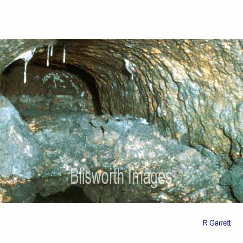
This shows one of the larger drainage headers along which men can walk (with a stoop). The staining indicates the normal height to which rust born in rainwater could rise. Often the drainage headers are set a few feet above the roof of the main tunnel running across the axis of the main tunnel. Many were linked together with longitudinal headers so that a layer above the tunnel is drained by the complex. Periodically the water was allowed to run into the tunnel through a brick-lined culvert emerging at the side or in the roof. | |
 |
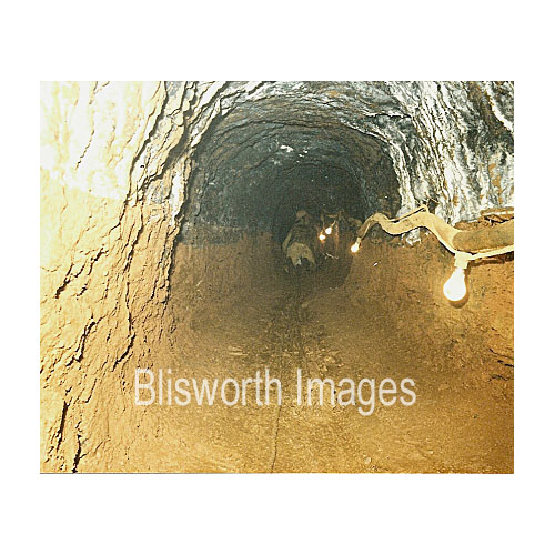
19-02 Even as early on as
1825, only twenty years into the life of the tunnel, the Georgian
engineers had noted gross movement as the clay all around the brickwork
displayed considerable plasticity. Fortunately there were only
isolated cases of this problem.
The initial task of the contractors was to survey all aspects of the tunnel, in particular a geological survey to establish the capabilities of the material around the tunnel. |
|
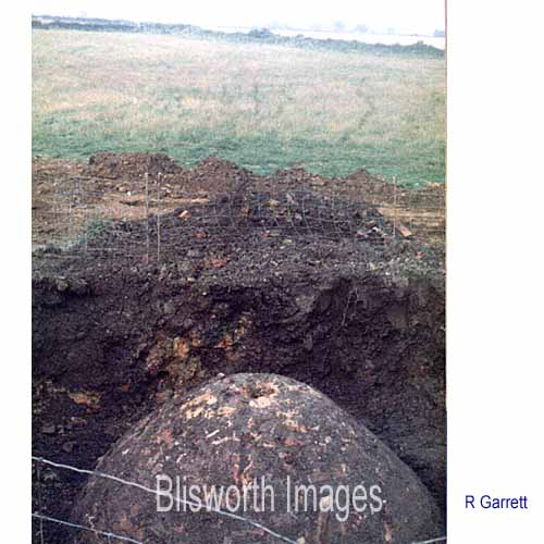 |
19-03 The survey extended to establishing all 21 of the original ventshafts though which excavation material was extracted during the build. Except for the five remaining as permanent vents (topped with a tower of brickwork) the shafts had been capped off in brick. It was necessary to establish by GPS exactly where these were situated so that allowance could be made for their jointing with the main tunnel. This one is in the middle of one of Don Taylor's fields near the highest point of the hill - the shaft would be around 35 metres tall. | |
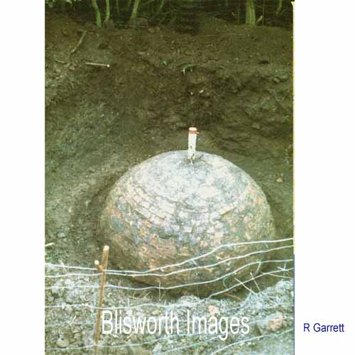 |
19-03a | |
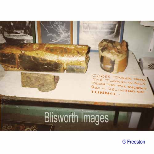 |
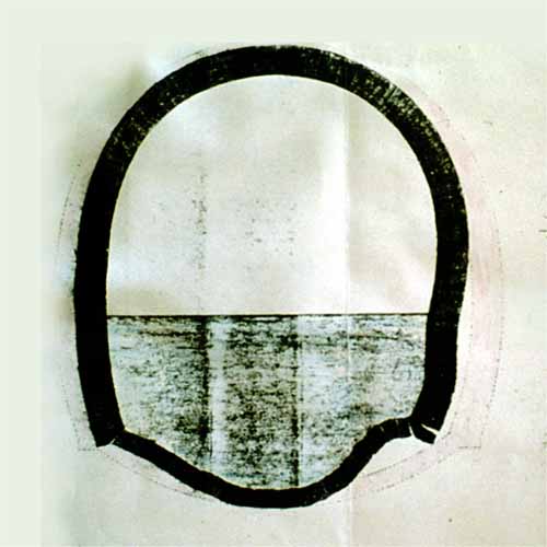
19-03b Samples were taken of the brick walling of the tunnel in various places to establish how much was damaged. | |
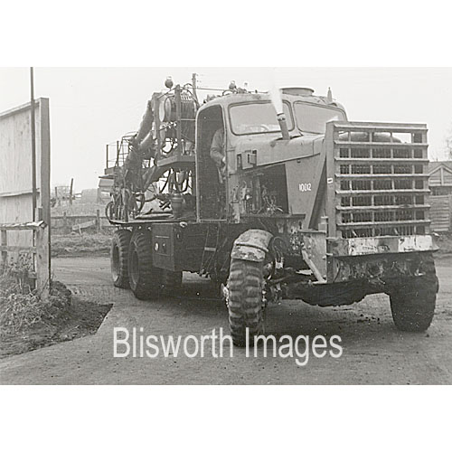 |
This was the vehicle, an ex WD Scammell, used to obtain the drilling cores in the picture above.
|
|
 |
George Freeston was on site many times in an
average week. He enjoyed every minute, took hundreds of
photographs - far more than were needed to tell the story and, for a
while, put himself in hospital with the strain of keeping up.
He wrote a memoir, in September 1984, on the closing actions in connection with the tunnel repairs, available here. |
|
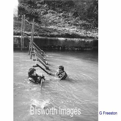 |
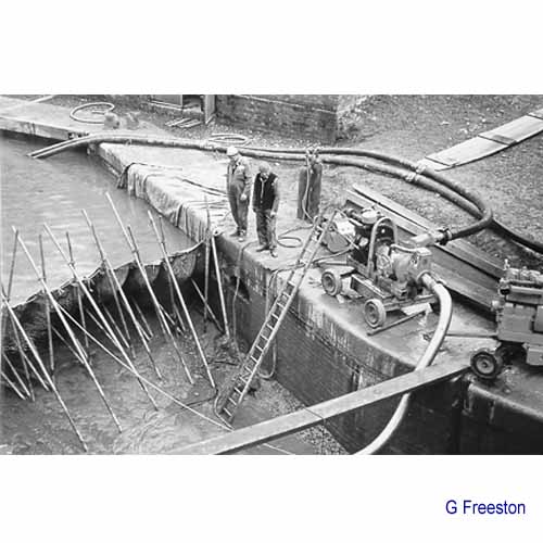
19-04 In the autumn of 1982, a couple of specialists started work to construct a dam across the canal about 50 yards from the north portal. | |
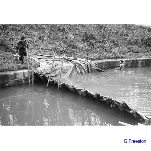 |
19-05 A network of iron stakes is carefully draped with a tarpaulin which will serve as a temporary retaining membrane for the water. | |
 |
19-06 A wooden barrier was also erected beyond the troublesome central third of the tunnel. The wooden barrier and this fabric one are called stanks. Once the pumping out of water in the tunnel had started, the tarpaulin was pressed against the base and sides of the canal and against the steelwork so achieving a good seal. | |
 |
19-07 | |
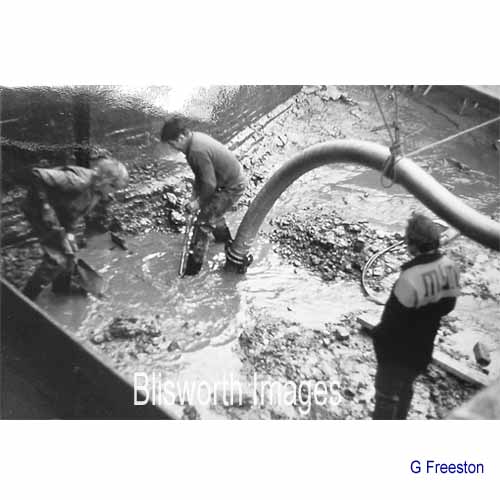 |
19-08 The work becomes more labour intensive as mud which cannot be mechanically dredged out has to be taken out by hand. | |
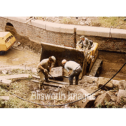 |
Whenever a section of canal is drained there always seems to be stone blocks left submerged from some previous job! George Freeston thought he knew the answer in this case. | |
 |
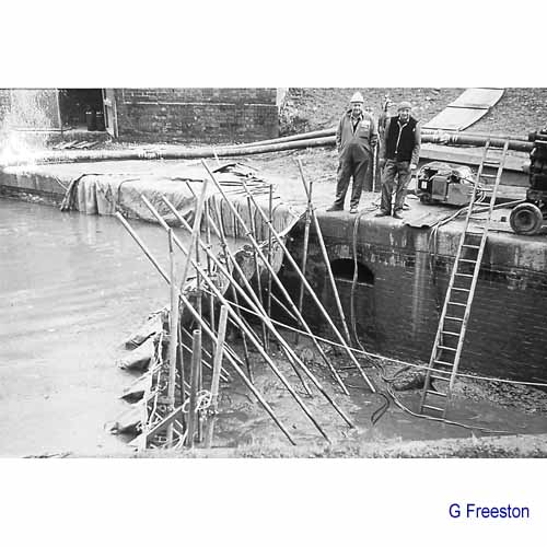
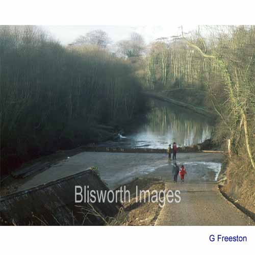
19-09 Eventually the tunnel is drained and the fabric stank is replaced by pile-driven interlocking pailings (the tops of which can just be seen) and the area can be prepared for vehicular access.
|
|
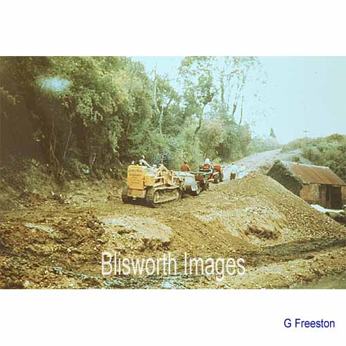 |
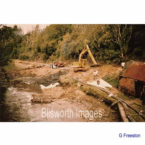
19-10 The steep path up to the Stoke Road is strengthened with thick concrete and 5000 tonnes of fill are brought in. | |
 |
19-11 By December 1982 what is achieved is a roadway capable of being extended into the tunnel right through to the other stank. | |
 |
19-12
|
|