|
Affordable Housing, Part I , Blisworth, Northamptonshire, UK. All pictures are presented at relatively low resolution. There will be hundreds of pictures on this site - there is an economic limit to the webspace available. Any interest in copies of a picture at a higher resolution (ie. clarity) should be directed through contacts given in the Blisworth "Round and About" parish council publicationor using the comment form on the home page. In some cases the pictures are not available due to copyright restrictions. However, permission has been obtained, where possible, to include them here. Printed below each image is the photographer's name, if known. |
||
|
Back to Home Page
This is Part
I
Part II
|
||
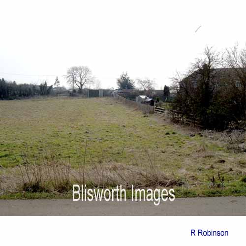 |
44-0b Late in 2005 the agreement was worked out for building what have generally been termed 'affordable houses', for the benefit of Blisworth people. It is permitted to consider land outside the village confines boundary for affordable housing and so this field near the parish fields was selected. Were the finances structured correctly and are the houses envisaged going to be affordable? These are controversial points but the published intent and the rules, not available generally until October 2006, seems worthy enough. The field selected is alongside the path to the football club and it borders the Courteenhall Road. |
|
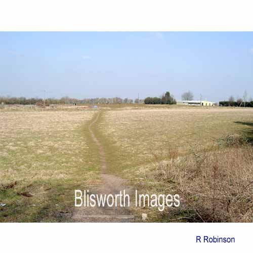 |
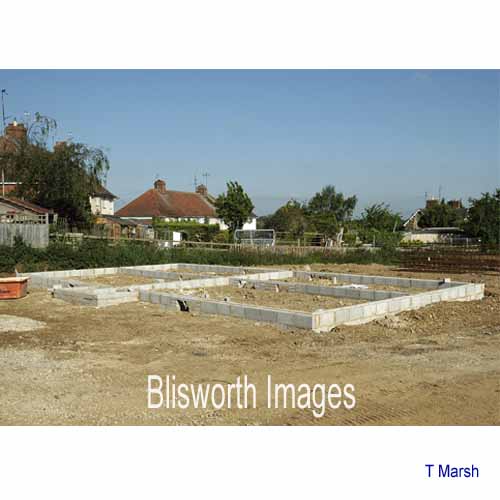
44-0a Early spring 2006, looking north from the Courteenhall Road where a pathway has been established through what has been recent set-aside land. This is where the main entrance road will go into the cul-de-sac estate comprising 21 houses. |
|
|
The name of the new road serving the new housing will be LADYFIELD |
||
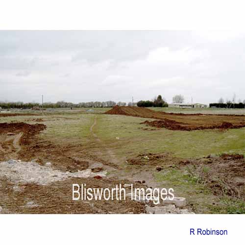 |
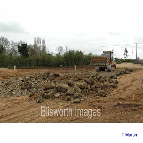
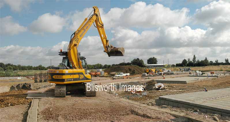
44-00 Same location - at the start of the project, 20th April 2006. Topsoil is removed and sold elsewhere except for a fairly large heap created at the corner of the site. |
|
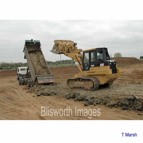 |
44-01 Actually, both the topsoil and about a yard depth of compressible soil needed to be removed and replaced with a more solid layer of heavy clay brought in from some other site. |
|
 |
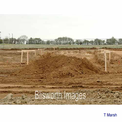
44-02 The clay will be the 'soil' in which the foundations are created for the new houses - as described below. The narrow posts with a height marker show the eventual ground level to be established.
|
|
 |
44-03 Clay is too expensive and unnecessarily solid to serve as the foundation for the road. Here they will re-fill with PFA, ie., pulverised fuel ash (being the powder used to cast 'breeze blocks' these days). | |
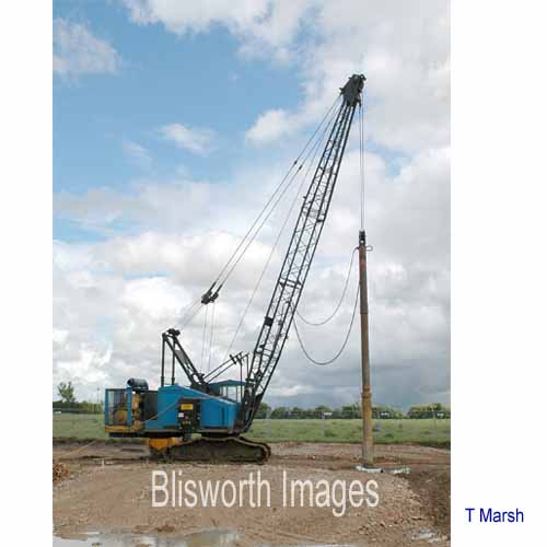 |
44-04 Having built up the layer of clay (and rolled it down hard) a hydraulically powered pile is applied to the clay and then slowly lowered. Being approximately half a ton in weight, it rams down into the clay: through the clay in fact and it continues to ram a total distance of up to 10 feet. The hole it makes is about a foot diameter.
|
|
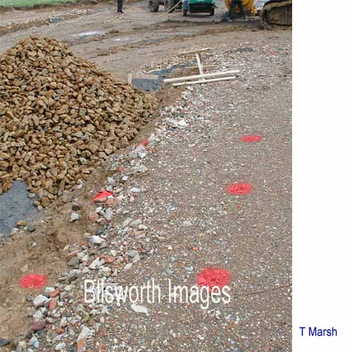 |
44-05 The pile driving crane walked all over the site making these holes, some 170 of them, exactly where someone had marked the ground with either a red or a blue dot. | |
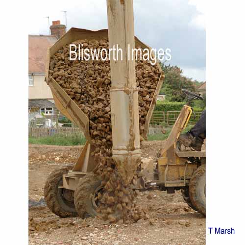 |
44-06 On first withdrawal of the pile, an operator was ready to pour some ironstone filler into the hole. A re-application of the pile and a top-up of ironstone, perhaps three times, saw the hole filled with a load bearing column of rubble. | |
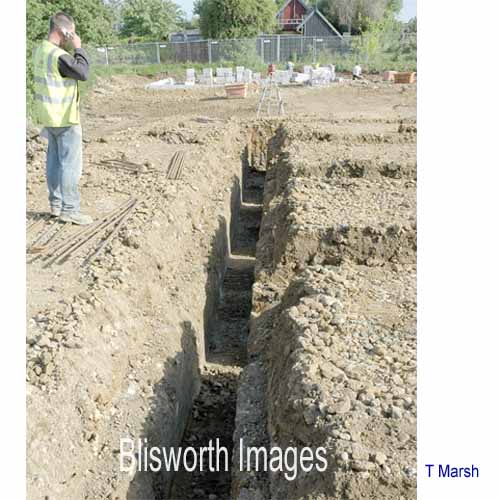 |
44-07 What appear to be standard footings trenches are carefully carved from the clay. Surveying comes into this work all the time. From places at the corners and at regular intervals along the trenches, the rubble- filled columns (previously created) extend downwards - to be the eventual supports for the houses. | |
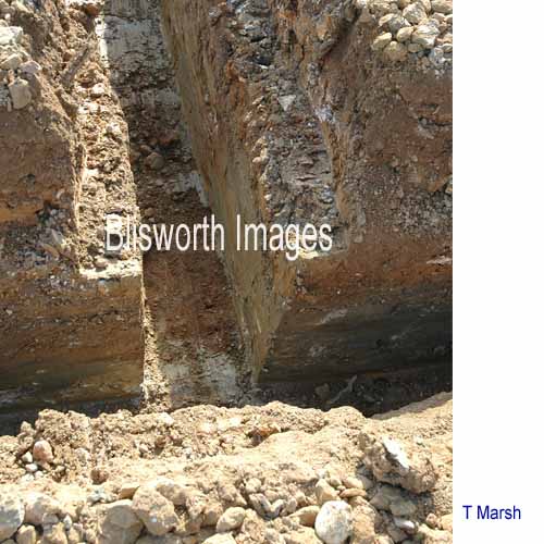 |
44-08 An important feature of the clay is that it can be cut into trenches with precision. | |
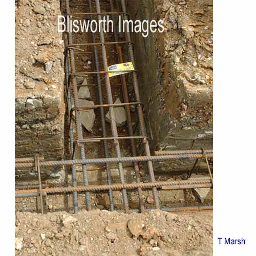 |
44-09 The steel lattice
work which will provide a steel-reinforced concrete beam is then placed
in the trenches, prefabricated to fit exactly at all in-line joins and
at corners. Little pieces of rock keep the steel away from the
sides and base of the trenches so that the liquid concrete will
thoroughly encapsulate the steel and prevent the steel from corroding.
A key point is that at such places as this junction, there is a rubble-filled column extending downwards into high strength soil. These reinforced beams are resting on the rubble columns and will not be exerting pressure on the clay base. What a contrast against the standard of foundations built in the village during the post war expansion! |
|
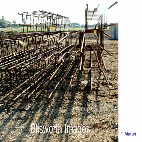 |
44-10 A stock of steel units. | |
 |
44-12 A picture of the liquid-concrete filling is missing. Once the concrete beams are finished the footings of solid concrete blocks can be built. Gaps in these footings are usually left for drains etc. - if the builders remember! | |
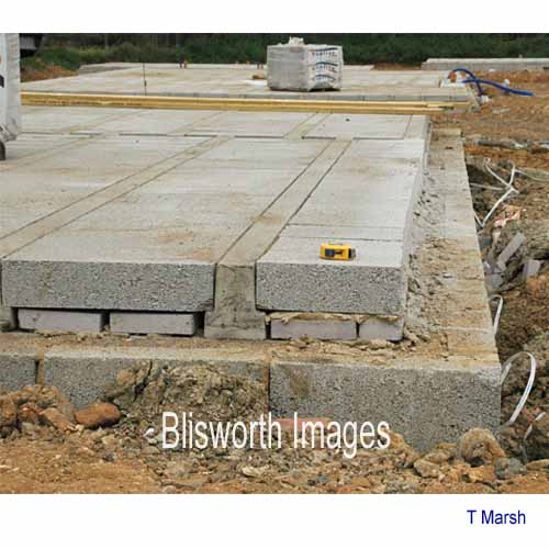 |
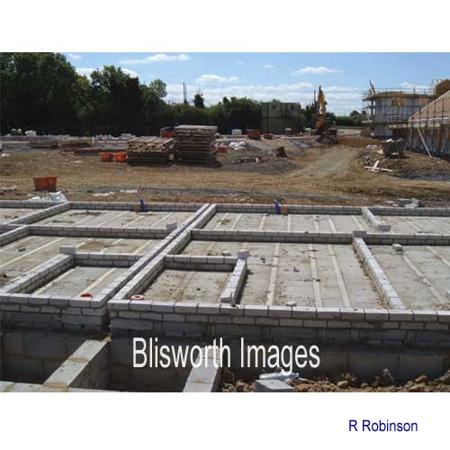
44-13 A solid base for the
ground floor is not done by traditional methods. Instead the area
of the rooms are crossed by made to measure pre-stressed
T-section concrete beams. Between these beams are laid a series of
concrete blocks. There is a locked-in cavity under this floor
which is of no consequence. If the area had tested positive for
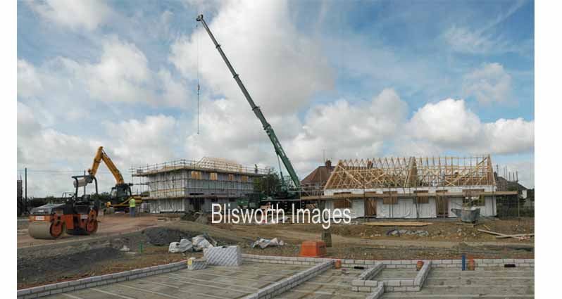
radon then the cavity would be continually ventilated. The next
two pictures taken on 11th July 2006 show some buildings in various
stages of completion and indicate the beginnings of a finished road into
the estate.
The final appearance of all the blocks of apartments is of a brick-wall exterior and wood frame interior |
|
 |
||
 |
||
 |
44-16 This shot shows more
clearly the pre-stressed concrete beams between which have been slotted
concrete blocks; the assembly thus forming a substantial floor.
Light-weight linterior walls may be placed anywhere on this
flooring. Note the three-inch cavity between neighbouring houses
which is provided for both fire and acoustic isolation.
|
|