|
Ironstone
Off-load Chutes and the SMJ Bridges
Tony
Marsh 19 December 2015
One
of the Ironstone Works images that was included in George Freeston's
collection
was suspected of being attributed to an incorrect bridge (out of the
total of four) which
cross the SMJ Railway cutting in Gayton parish. To "get it
right" raised a number of
practical issues - it all developed into something of a challenge.
 Introduction
Whilst
the arrival of the SMJ railway* inconvenienced the earliest ironstone
miners, it is clear that for a period that eventually extended to ~1950s
the miners made good use of the railway to ship out the ore. In recent discussions with Barry Taylor, author of an emerging book on
the SMJ railway,
the question was raised regarding the location of the extremely
distinctive ironstone off-loading
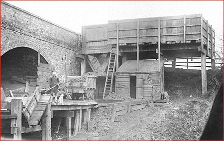
installation depicted in the website photograph 18-09 and also shown here in the inset. It
shows that the stages involved in the
off-loading were to (a) position horse and cartload of stone in the box at
road level (horse to the right), (b) open a hatch and the side of the cart
to let sufficient load down into a trolley-wagon running on a level set
of rails, (c) roll the trolley to its limit of travel and open its end
(and maybe tilt it) to (d) facilitate it being emptied into a chute over a rail wagon
waiting at a siding to the main SMJ line.
Introduction
Whilst
the arrival of the SMJ railway* inconvenienced the earliest ironstone
miners, it is clear that for a period that eventually extended to ~1950s
the miners made good use of the railway to ship out the ore. In recent discussions with Barry Taylor, author of an emerging book on
the SMJ railway,
the question was raised regarding the location of the extremely
distinctive ironstone off-loading
installation depicted in the website photograph 18-09 and also shown here in the inset. It
shows that the stages involved in the
off-loading were to (a) position horse and cartload of stone in the box at
road level (horse to the right), (b) open a hatch and the side of the cart
to let sufficient load down into a trolley-wagon running on a level set
of rails, (c) roll the trolley to its limit of travel and open its end
(and maybe tilt it) to (d) facilitate it being emptied into a chute over a rail wagon
waiting at a siding to the main SMJ line.
There
are two ways to determine which of the four bridges that cross the
Gayton parish cutting must have hosted this off-load installation. One
is to consider the evident geometry in the photograph with some
broad-brush dimensions extracted from the on-line Government Lidar survey data.
The other is to simply walk through the entire cutting examining and
photographing all four bridges from both sides - this proved to be very difficult and for some views impossible because of the virulent ivy
which has covered the bridge parapets and facings.
Bridges
The
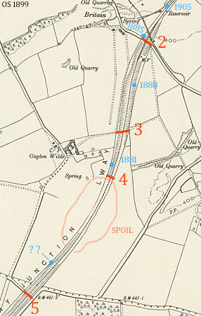
bridges are highlighted in red in an inset below. Working towards the south:
1. A road bridge near the station, demolished and irrelevant.
2.
Gayton - Blisworth road bridge. [It is actually labelled No. 3 in paint
at track level]
3. Public footpath bridge ("Oxenfordwey") running east from Gayton Wilds farm (which is
now a
small estate of four or five private houses).
4. Private farmers bridge - a facility for Mr. Darker (c.1860) whose
field was divided into two parts.
5. Saltway bridge - a road bridge continuing a re-routed connection
between Tiffield and Gayton, also crossed by the Saltway.
 In the
historical records there is already evidence of a shoot (sic.) being
once installed at road bridge No. 2. Only the box for the cart is shown in
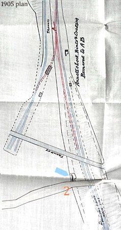
this diagram, arrowed in blue in the inset. The plan, dated 1905, was mainly to convey early 20th century changes to the
tramway, blue crayon, that lies to the west of the cutting. It was copied and
supplied by Barry Taylor. Perhaps this chute is the same one as depicted
above but first consider the dimensions of the four bridges, as
indicated in the Lidar imagery..
In the
historical records there is already evidence of a shoot (sic.) being
once installed at road bridge No. 2. Only the box for the cart is shown in
this diagram, arrowed in blue in the inset. The plan, dated 1905, was mainly to convey early 20th century changes to the
tramway, blue crayon, that lies to the west of the cutting. It was copied and
supplied by Barry Taylor. Perhaps this chute is the same one as depicted
above but first consider the dimensions of the four bridges, as
indicated in the Lidar imagery..
| BRIDGE |
SPANS |
HEIGHT
(m.) |
CUTTING
WIDTH (m.) |
| 2 |
3 |
9 |
35
- 40 |
| 3 |
3 |
11 |
50
- 55 |
| 4 |
1 |
5.5
- 6.0 |
18 |
| 5 |
3 |
9.5
- 10(a) |
40 |
| (a)
measured by plumb-line as 10.4 metres |
So for this
"shoot" to work,
an additional wooden chute would have been used which could connect the
off-load arrangement at the top of the embankment with the wagons waiting
below in a siding. If placed by any one of the 3 span bridges then it would have been about
20 metres long and sloped at about 30 degrees. No chute by bridge No.
2 is shown in the plan and so was perhaps taken away by 1905. All
the bridges with the exception of the private bridge No. 4 are similarly
proportioned. The private bridge is located where the track is
substantially level, ie. reached its maximum height before descending
towards Tiffield at a point where the depth of excavation was at a
minimum. A significant cutting,
excavated by hand and barrow, extends for over a mile and this probably
presented a problem regarding where the spoil needed to be taken. Geometry
Photograph 18-09 tells us that the short
piece of railway for the transfer trolley is near the same level as the
camera lens. Given the man in the picture was about 1.8 metres tall, one can estimate
that the road level is approximately 4 to 4.2 metres above the short
rails. The camera tripod would be 1.5 to 1.9 metres high and standing
firmly perhaps on a wagon floor which would be another metre from the
track. These estimates yield a bridge height, road to track-bed, of 6.8 +/-
0.3 metres (and
if the camera had been placed on the ground at more-or-less track level, this
would bring the estimate down to only ~6 metres) suggesting bridge No. 4
as the likely location. Bearing in mind however that the
angle subtended between the axis of the camera and either the bridge face or the track must have
been in the region of 45° and knowing that common cameras c. 1900 could
accommodate a field of view normally ranging over only from 25° to 50° the inevitable
'conclusion' must
be that, for bridges Nos. 2, 3 and 5, the camera would have been floating in
midair !
Expedition
First the bridges Nos. 2 and 5 were inspected at road level to help
determine "where would the camera be located" and make some
assessment of brick facings and copings. Then an outing, starting from the stairs at bridge No. 5, confirmed that No.5
was never the host for the chute installation because of brick and coping
stones style and the fact that the side arch was much further away from
the boundary of the cutting. Bridge No.4 was a reasonably close match at
first sight. Some aspects of the brickwork on the north face matched well but it was
largely covered in trailing ivy. The face was photographed but attempts made to achieve a good schematic fit with the
historical image were unsuccessful. Brickwork colour (courses of black brick), copings and
the shape of the arch were also a poor match. It seemed likely the brickwork
was the original but the coping was built with corbel black bricks
rather than slabs. The main problem in achieving a good match was because
the single arch was very broadly elliptical.
 Therefore
my verdict was open until I could prepare an 8" shaving mirror
attached with its swivel onto a 2 metre pole to enable a close examination
of brickwork from above at the heads of the side arches in the 3
span configurations. There is no doubt at all that the verdict is the 18-09
installation was definitely at bridge No.2, just where it is drawn on the north
side in the 1904 plan shown above. The
camera
angle relative to the bridge face was re-estimated to be about 37° when it was realised the bridge and its arch were considerable
foreshortened. This had caused confusion over the horizontal distances between
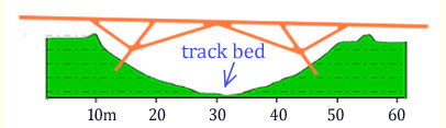
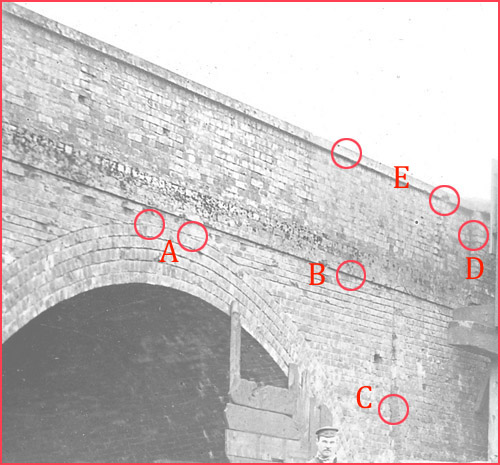
features. Referring to the diagram at the end of this article, the
position and appearance of items A,C and D were in good accord. It appears
that the parapet was rebuilt at some stage because the degree of
out-sailing of courses at the base of the parapet was not a good match.
Therefore
my verdict was open until I could prepare an 8" shaving mirror
attached with its swivel onto a 2 metre pole to enable a close examination
of brickwork from above at the heads of the side arches in the 3
span configurations. There is no doubt at all that the verdict is the 18-09
installation was definitely at bridge No.2, just where it is drawn on the north
side in the 1904 plan shown above. The
camera
angle relative to the bridge face was re-estimated to be about 37° when it was realised the bridge and its arch were considerable
foreshortened. This had caused confusion over the horizontal distances between
features. Referring to the diagram at the end of this article, the
position and appearance of items A,C and D were in good accord. It appears
that the parapet was rebuilt at some stage because the degree of
out-sailing of courses at the base of the parapet was not a good match.
Regarding the camera
position one must conclude that the stanchions or the struts for the wooden tramway
bridge must have provided support at about the right height and that the
photographer must have had access to a very long lens tube and struck lucky in
regards to catching the dog 'frozen' enough for the inevitable long exposure. It is a shame the photographer did not record the
rest of the chute
and the equipment at track level that would have been necessary to control
the energy of the descending rocks.
Other points are made in the Appendix.
Chutes
Finally we turn to a review of all the known off-load-to-railway installations along
this cutting and the situation is shown in this third inset, based on OS
1899. Working from
north to south each chute is identified by date (plans were kindly
supplied by Brian Taylor):
1905 a Wheldon application was to connect the tramway to the
main line for the installation originally set up by George Pell, as
mentioned above.
"1885" - the date signifies 1865 - 1900. This is the
"shoot", probably for Pell, marked at bridge 2 that has turned
out to be the subject shown in image 18-09. It is drawn
incompletely in the 1905 plan, therefore assumed in disuse by then
although sidings on the west side are still in evidence in the
1905 plan.
1888 an application for sidings on the east side
includes an indication for a chute as marked which one assumes served the
mining in the adjacent field (with/without a tramway?). Sidings on both sides of the main
line are unlikely and it is probable that the north end of the siding did
not actually reconnect with the main line. Interestingly, Tonks (p. 35)
records that a later use of this off-load location was agreed with T. &
I. Bradley (Darlaston) in 1912 and included a proposal to quarry a massive 200 acres
but nothing came
of the proposal. It serves to illustrate the 'state of flux' in ironstone
mining that is now difficult to document.
1881 another Wheldon application for sidings on the west side
but showing no
chute. Note that one of Tonk's maps show tramway sidings running near the
cutting at this approximate location and a map referring to Wheldon's
mining shows a tramway running close to the main line with a chute also
marked. This
is quite near to bridge No. 4 but not adjacent to it.
Finally "?" At a short distance north of bridge No.
5, there is some striking embankment disturbances that might have accommodated a
chute. It is on the west side and marked in the inset plan at the
point where Lidar indicate the disturbance. Perhaps
this feature was connected with the management of spoil. Also notable
in the Lidar data is a large 2 to 3 metre high embankment in the fields on
both sides of the railway, between bridges Nos. 4 and 5. It is assumed
this is spoil from the original 1860s railway excavation and perhaps
intentionally limited to a
collection of potentially
useful iron-ore, with other burdens discarded. One might
surmise that a possible chute here could have been used, at least
initially, by the mining concerns to recover that iron-ore and send it
north by railway. The existence of normal surface mining work in this
southerly field has not been noted by Tonks. The landowner (The Darker
family)
recorded a feature labelled "Old Spoil Bank" on their estate map
(1791) when it was updated in red ink to show the line of the railway but
shows no access from the fields.
 Whilst
the arrival of the SMJ railway considerably inconvenienced the surface
miners, it is clear that for a period that eventually extended to ~1950s
the miners made good use of the railway in order to trans-ship to either the
Grand Junction Canal or to the Birmingham to London main line. Records
show that the relatively audacious overhead tramway used to work fields to
the east just north of bridge No. 2 was in fact in place before the
SMJ railway cutting was made. George Pell's sidings beneath that gantry
once led to a tramway that served a siding beside the main line (a mile
away). That tramway had to be
moved to the west, out of the way of the cutting. Also, the gantry had to be
rebuilt to cross the SMJ cutting, which is around 35 - 40 metres wide. The inset perhaps helps to visualise a timber construction
using beams of up to 10 metres long. It was burnt down in 1929.
Whilst
the arrival of the SMJ railway considerably inconvenienced the surface
miners, it is clear that for a period that eventually extended to ~1950s
the miners made good use of the railway in order to trans-ship to either the
Grand Junction Canal or to the Birmingham to London main line. Records
show that the relatively audacious overhead tramway used to work fields to
the east just north of bridge No. 2 was in fact in place before the
SMJ railway cutting was made. George Pell's sidings beneath that gantry
once led to a tramway that served a siding beside the main line (a mile
away). That tramway had to be
moved to the west, out of the way of the cutting. Also, the gantry had to be
rebuilt to cross the SMJ cutting, which is around 35 - 40 metres wide. The inset perhaps helps to visualise a timber construction
using beams of up to 10 metres long. It was burnt down in 1929.
Reference:
Eric Tonks, The Ironstone Quarries of the Midlands, Part III - p39
(but lacks detail at this level)
* the "SMJ railway" is more correctly named the
Northampton and Banbury Junction Railway
Appendix:
The first picture shows the features in brickwork listed as testable item
The second
demonstrates a recent picture taken through a hedge from a vantage point
that was maybe 3 or 4 metres too high, at the edge of the cutting to the
east and therefore from a considerable distance using a 200mm telephoto
lens.
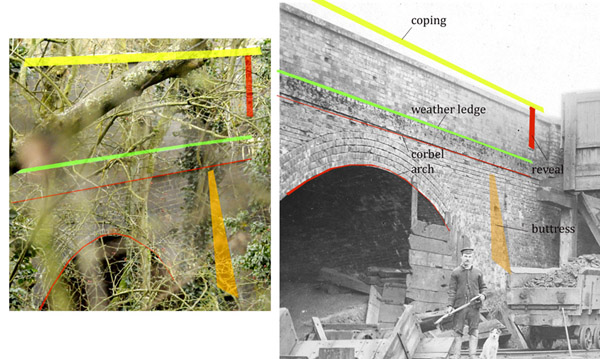
The
bridge details are traced with coloured shapes in a separate Photoshop
level and this level is then applied to the historical picture. All the
details were in one geometrical plane and so neither
of the 'vantage point' details, mentioned above, would have challenged the
ability to morph the bridge details to fit the historical picture. It would
appear that the parapet has been rebuilt 4 or 5 brick courses higher, the
brickwork reveal was rebuilt nearly a metre towards the bridge centre
and evidently there has been modifications to provide a more substantial buttress.
All of this work was done once the loading "box" had been removed. Anyone
reading this might be unconvinced and suspect the "right bridge"
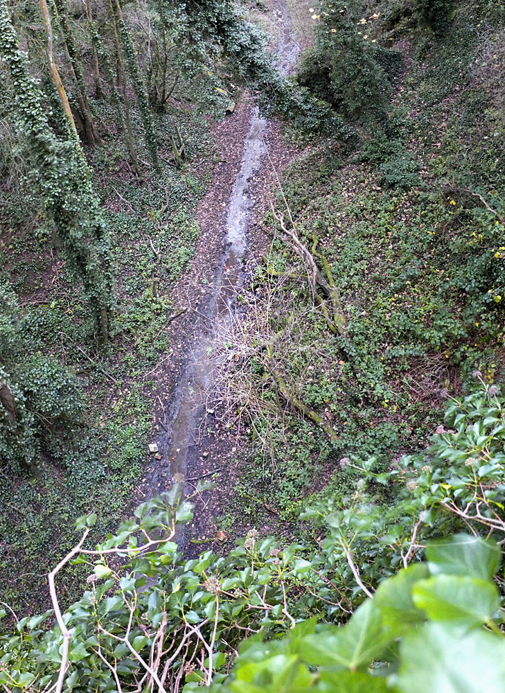
has not been found. There is only bridge No. 3 (Gayton Wilds) left to inspect
in a thorough manner but it is
covered in ivy (see view to the south
at bridge 3) and there is an even poorer chance of obtaining a
interpretable shot
through the opposite bank hedge. If there is a bid for this work I can
help with a map and a mirror! I
am forced to conclude that I was
right in the first place: the camera was an ordinary one and was really in "mid-air" and
there must have been a wooden bridge temporarily set across the cutting
(perhaps part of the tramway bridge structure) on which the photographer
could have stood. Basically, the 18-09 picture has too much perspective
slanting of level lines for it to have been taken with a long lens.
|