This article contributed, in part, to Adam Porter's
article on the tunnel in Canal Boat January 2014.
A REVISED STORY OF THE CONSTRUCTION
OF
BLISWORTH TUNNEL
Tony Marsh February 2007
This article is a re-write of one placed
on this website in October 2005. The aim of the
re-write is to improve clarity - there is no change to the information
presented.
Claim: This account
justifies the statement that two, not one, lines for the tunnel were tried
before the
successful line was adopted. It accounts for all of the known evidence for
subsidence on Blisworth Hill,
including the strangely off-line vent near to Buttermilk hall farm, and provides
an explanation for the
remains of what appears to be a water-course in a field known as The Park.
It also prompts a suggestion
for why a part of the canal bank is anomalously steep and why there remains only
a narrow course for the
hill railway near the same place.
 Introduction Plans for the tunnel through
Blisworth Hill were deposited in 1793 and the northern part of the canal had
been dug as far south as Blisworth by 1796. The deposited plans show the
configuration of the canal (ie. its bends along the 'Parliamentary Line')
outside the tunnel in accord, more-or-less, with the layout we now have.
Attempts to scale from these plans are hardly worthwhile. The early attempt
to pierce the hill with initial headings (narrow 'pilot' diggings) was reported
to be dogged by excess water and some brickwork collapse. Work continued for
many months on draining the hill, especially near the centre and south end. It
was then reported that the 'works were out of line' which we take to mean that
the line of vertical shafts (the bases of which would be joined by headings)
were not in a sufficiently good straight line. It was then resolved to start
again with a new alignment; that is, dig fresh vertical shafts and the new line was said
to be 150 yards to the west of the aborted attempt at the south and a short
distance to the east at the north. In the new alignment there is some reference
to the line consisting of two tunnel sections joined by a short curved
'open-air' section near the north end. This complexity is later dropped and the
project proceeds to completion in 1805 along the line we have today. This
summary may be filled out with considerable detail by reading David Blagrove's
book "Two Centuries of Service" available at the Museum at Stoke
Bruerne. He has based his account primarily on the project minutes of the Grand
Junction Canal Company.
Introduction Plans for the tunnel through
Blisworth Hill were deposited in 1793 and the northern part of the canal had
been dug as far south as Blisworth by 1796. The deposited plans show the
configuration of the canal (ie. its bends along the 'Parliamentary Line')
outside the tunnel in accord, more-or-less, with the layout we now have.
Attempts to scale from these plans are hardly worthwhile. The early attempt
to pierce the hill with initial headings (narrow 'pilot' diggings) was reported
to be dogged by excess water and some brickwork collapse. Work continued for
many months on draining the hill, especially near the centre and south end. It
was then reported that the 'works were out of line' which we take to mean that
the line of vertical shafts (the bases of which would be joined by headings)
were not in a sufficiently good straight line. It was then resolved to start
again with a new alignment; that is, dig fresh vertical shafts and the new line was said
to be 150 yards to the west of the aborted attempt at the south and a short
distance to the east at the north. In the new alignment there is some reference
to the line consisting of two tunnel sections joined by a short curved
'open-air' section near the north end. This complexity is later dropped and the
project proceeds to completion in 1805 along the line we have today. This
summary may be filled out with considerable detail by reading David Blagrove's
book "Two Centuries of Service" available at the Museum at Stoke
Bruerne. He has based his account primarily on the project minutes of the Grand
Junction Canal Company.
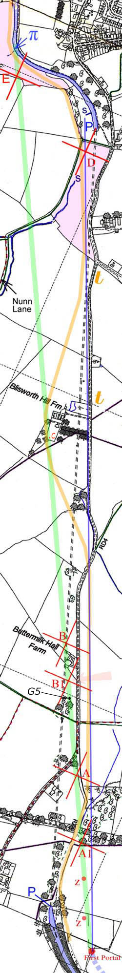
A little more detail can be
gleaned from the evidence on the ground. A recent survey has been
completed and the information, some of it entirely new, is presented in the
figure to the left. The figure is based on an old OS map and the section on view
is a strip of land running from the NNW to the SSE. In other words, to save
space in the browser window, the map has been rotated somewhat in a clockwise
direction. This is evident from the appearance of some reference points in red
eg. E and D which can be seen to the left. So, let's go
through the evidence . . .
Fist the features labelled in
blue; the Greek pi symbol, π
(the browser may/may not successfully show this symbol) refers to a bend in the canal where the western bank is much
steeper than anywhere else in the whole project. I return to this in a
discussion near the
end. The culvert entrance and exit labelled 'S' highlights the underground
path provided for Fisher Brook by the engineers so that the water discharges
safely into the canal. North and south portals of the finished tunnel are
labelled 'P'.
In establishing the headings for
the final tunnel, 22 vertical shafts were dug down to a datum level having
carefully aligned them all along a straight line which appears to have Stoke
Bruerne church tower as its southern end point, being a 'target' visible quite a
long way over Blisworth Hill. The headings were dug on two faces at the
bases of the shafts in order to establish a continuous heading. When the tunnel was repaired in 1982,
surveyors found all these shafts and checked that they were safely capped with
brickwork. They needed to know their precise positions prior to any repair
work. The marks labelled in red relate mostly to 'off-line' shafts,
or rather, the evidence of them. They were created whilst engineers c.
1797 pursued earlier,
unsuccessful, tunnel alignments and are described below. Some of these
locations indicate land
subsidence and the area near them can be assumed potentially dangerous to the public.
E. A one foot
depression over an area some 6 to 8 feet across. This is centred on a
small plateau of land near a field fence - see photograph which is taken from a
low vantage point to the east in order to illustrate the 'plateau'. The
feature is located in a field known as The Park or Park Slopes - coloured lilac.
Note the counter argument regarding this feature given in the series of
photographs.
D. A low hump of
spoil on which a electric distribution post happens to be placed. In 1976
a large hole appeared at the centre of the hump and the pole keeled over. In this photo the pole is shown sawn off while repairs were done. In the
distance is the Stoneworks farm house. The feature is located at the north
end of a field known as Fisher Close or Fishweir (also coloured lilac). There was
once a deep depression in Fishweir (partly filled by the traverse of a
horse railway - orange line, see below) which is believed to have accommodated a large medieval fish
pool. The horse railway is also known as the hill railway, tramway,
plateway, etc.
C. A feature near
Blisworth Hill farm which was discounted and is therefore not discussed.
However the reason it was
discounted is based on the farmer's statement that some ground subsidence that I
picked up on at this location actually related to a swimming pool. Another
farmer, an acquaintance to the first farmer, 5 years later has told me that the
idea of a swimming pool just there is nonsense. So maybe location C is
really associated with the proposed first tunnel. I will not be able to
confirm this without offending the first farmer ... oh well!
B. A particularly
tall brick chimney mounted over a shaft that is in use over the existing
tunnel. There is good reason to suppose it was first dug for one of the
unsuccessful alignments.
B1. A particularly
short (6 feet) chimney over an off-line shaft that is connected to the existing
tunnel by a slantwise heading. This vent can be inspected from the Stoke
Road in the direction of the pink coloured arrow. Associating this vent
with an earlier tunnel alignment provides a reason for it being built, yet still
useful as a vent, 40 feet
off the line of the finished tunnel. Its diminutive stature is a puzzle.
G5. This is a
feature just south of B1 as indicated in a diagram prepared by George
Freeston in May 1985. He doesn't say what G5 is on the diagram but
it is a safe bet that it marks another ground collapse. G5 is
exactly on the green line - see diagram as a footnote to
this article.
A. A small area at
the edge of a field that has been fenced off by the farmer. It had sunk in
the past. Interestingly, this feature was re-discovered in the recent
survey by noting that T. W. Millner, regional chief engineer GJC
Company, found a sunken feature in 1922 and gave,
in a letter (GF Collection 1996 - Canals), its
'co-ordinates' as 1564 feet along the tunnel (from the south portal) and
off-line to the east, perpendicularly, by 200 feet. It is probable that no
one, until now, has made use of the data in Millner's letter. Transferring this data
to a map placed us exactly at the feature - photo taken from the fenced path.
A1. A sunken feature
that has dropped 10 feet in the recent past and after refilling stands at 3 feet deep
at present. It was pointed out to me by the farmer.
Z. The same farmer
drew my attention to two zones of rather broad subsidence which have become established in
the arable field. (no photographs)
First Portal. The
same farmer agrees with my supposition that the first portal at the south end
was located here. (no photograph)
Grouping the Features.
All the features listed above, except for one - D, are on a good straight
line. It is therefore supposed that they were created to enable a continuous
heading to be established from the first south portal to one at the north end
that is tentatively labelled 'Greek pi',
being in line with
the bridge at the mill.
The 'good straight line' can
be appreciated scientifically, in that there are a total of seven features which
support each other with a high precision, excluding the location of the first
portal and the feature marked E. That seven such features might occur as a
joint coincidence is very improbable indeed - in other words, the alignment is
there for a supposed good reason. This is the chief revelation of this
article. That a less clear alignment simultaneously seems to exist for the
turn in the canal at the north end, point E and the first portal provides the
'good reason' and prompts us to write the revisions to history - see below.
Let us assign the name First Portal Green to this
line - FPGreen
for short. The feature at D is presumably associated
with another set of headings (also using the initial south portal?) which we name FPBlue.
There is little to define it other than the feature at D but the farmer
has pointed out that the stream seems to disappear underground now at the point,
between A and A1, where it crosses FPBlue (the stream is
marked blue in the map). The point at which the stream disappears should
be regarded as another potentially dangerous area. Knowing
that the hillside was pierced by numerous drainage headings, especially at the
south end, we cannot attach much significance to this point.
In any case, FPBlue
does fit the description for the alignment revision mentioned in the
introduction and therefore, on the face of it, FPBlue might be supposed
to be the second unsuccessful alignment. However, the fact that FPGreen and
the final tunnel both pass through (or under) the vent at B, being a
particularly tall chimney, is very probably significant. It bears on our
view as to the order in which the two alignments
were attempted - in fact contradicting the supposition above, ie. FPGreen
followed FPBlue.
Writing the History ?
The status of the perceived straight line
given in the sections above raises the proposition that FPGreen was
really attempted. In the paragraphs labelled "Try this Idea" there is
my interpretation. Note there is a piece of evidence from the management minutes
was unearthed by George Freeston:
Minute
of 17th May 1796: (paraphrased) that the agreed line through the hill be taken
by "crossing the line of the present ruins near the north end and to enter
the ground a little to the east and come out about 130 yards to the west of the
present line, being the best and most eligible line that can be
adopted" So, a variance was proposed... Let's call
this FPWhite
Minute of 7th June 1796: "that the tunnel be executed on the original
line" and, in the margin written Original line to be pursued.
This sounds like FPWhite
was really FPBlue...
Try this Idea For reasons of wishing to use the two
completed halves of the canal, while the tunnel was being built, the engineers
established a toll road in around
1795 to join Blisworth with Stoke Bruerne.
The road, which is now called the Stoke Road and is clearly shown running the
length of this map, was by the requirements of the Parliamentary Act
to run as close to the line of the tunnel as feasible and this is the case for FPBlue.
The toll point on this road has been indicated at one of the two orange letter Ts
on the map. A horse railway was established in 1800 because the horse and carts used on the
road were an inadequate means of transport. The horse railway was used until the tunnel project
was finished in 1805 - its path is shown approximately by the orange line in the
map. It too was supposed to follow the line of the tunnel but, from an
inspection of the topography, it is clear
that it could not do so whilst achieving an even grade, being an important
consideration for horse-drawn vehicles. Actually, for some
of the way, it followed FPBlue but lay directly over FPGreen
near to Blisworth Hill Farm where it runs behind the farmhouse. This could
be coincidental as the farmhouse was established at some time
before 1806 (Grafton rental records - farmer Samuel Wilson).
Let's propose here that the
progress in the project was made along the lines given here and then give a
speculative account of the story of the project:
FPBlue and Toll
Road > [Revision 1] > FPGreen and
Horse Railway > [Revision 2] > Final Success
It is necessary to assume that
the action to attempt FPGreen was never minuted by the management and
that it was either quietly agreed with the Duke of Grafton or it was carried out
illegally. Of course we shall never know. No measure of surprise
need be felt as sharp practice and creative book-keeping were endemic in society
circa 1800. We must be thankful that the real heroes of the project were
the engineers. Within the limits of what was known then of tunnelling
expertise and
what we know now of the geology, the achievement is to be appreciated by all as simply
monumental.
So, what happened in the two
Revisions?
Revision 1
The earliest work on the tunnel c. 1794 was carried out by Messrs. Jones and Biggs.
These contractors were soon laid off as the chief engineer, Barnes, took over
the work in 1795. Biggs had pulled out and Jones was found to be too slow
and have presided over poor brickwork. Although 'in charge', Barnes was
presumably absent dealing with other parts of the project. By the end of
1795, work was nearly at a standstill. [see Blagrove] Mention
is made of excesses of water without indicating whether this was at the north
end or the south end, or both. Villagers these days know that Fisher Brook
is extremely variable in volume, being fit for toddlers to paddle in (in high
summer) and of sufficient volume to supply 50 cubic yards a minute of water at
other times (after a few days of very wet weather). The brook is the
result of rainfall collection over an area of 3 square miles and is capable of
filling a major works in hours. It is possible that, in trying to
establish the north portal for FPBlue, the rages of Fisher Brook had
taken them by surprise - in any event the engineers must have become terrified
by it. Indeed, by choosing the 'cranked' course of the canal in its
approach upto the intended tunnel entrance, the engineers had picked the
approximate course of the brook and had probably invited inundation.
The rather radical revision to adopt the
line FPGreen would bypass all the problems of Fisher Brook which could
then be easily ducted to pour into the canal from the east, not far from the
bridge near the mill. Two other advantages were to arise from the
plan. One was that a long excavation into the hillside would not be
needed, thus saving labour. The other, as far as the villagers and
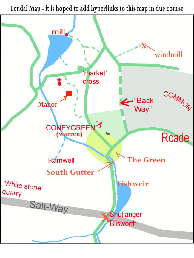
probably the Duke of Grafton were
concerned, was that a place known as 'The Green' (South Gutter Green on the 1729
map) would not be sacrificed to that long excavation.
To
even consider the direct line, FPGreen, was to go against the terms of
the Parliamentary Act and the detailed plans therein. How could a band of
engineers, led by Barnes, backed by managers in London, do that? Evidently
there was an arrogance, partook also, probably, by the Duke of Grafton that
reasoned, "Look, this is a better plan, actually, we'll go this way and
codge-up the terms later - Parliament will see our point of view! By the
way, let not our ideas enter the records..."
Does this sit well with what we know of the 1780 - 1820 times? I leave
others to comment.
Revision 2
By the evidence of a number of shafts, the FPGreen line was worked on for
quite a time. No doubt a north portal would have been created at a point
near that labelled with a Greek pi. The line was eventually
abandoned. It could be that, in working the tunnel from the south portal, the
engineers had experienced basically their first real encounter with the problems of underground
water and they were unprepared. It could be that their work collapsed.
There are two depressions in the fields to the north of the south portal, marked
by red dots at Z in the map, which certainly line up with FPGreen.
A collapse, of course, could have occurred at any time since.
If there was a drastic problem with FPGreen,
the engineers would be forced to again rethink. They had an option to
return to approximately the Parliamentary Line if the problem of Fisher Brook
could be overcome. Comparing FPGreen with the successful line, one
cannot help noticing that the approaches to the portals at both ends are
distinctly different. For FPGreen the tunnel would begin with very
little ground overhead, at both ends. For the final line, a long
excavation into the hillside (as originally planned, it seems) was adopted.
Whether the FPGreen portals with their brickwork were giving trouble we shall never
know. In abandoning the portals the one at Greek pi would have been
dismantled. It is at this time the engineers were mostly engaged on
'draining the hill' and many months would go by as they prepared for the final
line. The horse railway would have been completed and, to a degree, the
pressure would have been relieved.
The
Horse Railway: It is a fact that the path of the railway
generally shows room for a southbound and a northbound rail placed side by
side. Furthermore, sleeper stones have been found in 4 lines at places on
Blisworth Hill. If one walks south, starting at the bridge near the mill,
there are to be seen in the first field two levels, side by
side, for the
railways. As the path skirts the first bend in the canal, the
accommodation curiously narrows to that sufficient for
only one railway and the ground
appears to have slumped somewhat. Furthermore, the bank of the canal is
much steeper at the bend. There is a minute referring to a discussion
about the safe angle to adopt when cutting the long excavations.
Barnes, it seems, wanted the angle to be 20 or 25 degrees as this is the angle
everywhere else. But someone asked that maybe the angle, generally could be
steepened to reduce
the amount of spoil to be removed. The minute records the suggestion was turned down. So,
given the strong preference for a gentle slope at ~20 degrees, why is there a steeper bank just where the accommodation for the railway had
narrowed?
One
answer is this: A line was adopted for the pair of railways curved over the
ground just south of the portal at Greek pi and continued over the hill -
in other words it was innocently placed very close to the edge of the eventual canal
works but thought safe at the time it was placed. When it became clear that a new line
for the tunnel was needed, the portal would be need to be removed and then the course of the
canal excavation would be close to the
railways. Barnes must have relented his grip on excavation angles and perhaps
left a bit of the portal brickwork in place, for a while, so as to support the
railway nearest to the canal, this being satisfactory and not requiring further
excavation on the other side of the railways (the west side) to make further
accommodation. He knew that stability for the railway was not a long-term
requirement.
Another
partial answer is this: A 1947 aerial photograph (NRO) of the area
shows that the footpath was located some 3 or 4 yards further south in 1947
compared to now. (It is an intention to overlay Google and RAF maps in due
course) The bank seems to have slipped and the slippage could have created
a steeper descent to the canal. Now the slippage seems to be quite
noticeable at the turn in the canal and we need to ask why - maybe the previous
excavation of a portal!
An attempt to preserve the portal at Greek
pi (but perhaps rotating it slightly counter-clockwise) for the sake of the railways would perhaps have
generated the idea to have two tunnel sections (as mentioned in Blagrove's
book). There would perhaps have been planned a short section of tunnel to
replace a substantial part of the deep excavation, followed by an open curved
section leading to the north portal as we know it. The problems regarding
Fisher Brook would be solved if the brook could then be ducted over the short
section. What happened, presumably, was that a new way to deal with the
brook was found and the complexity of the extra section could be dropped and the
risk to the railways deemed minimal.
Fisher
Brook: In the now out of print book "Blisworth", available
on this website, a theory is presented for the diversion of the brook.
Starting from Fisher Close, a uniformly graded line could be found which runs
north and parallel to the railways. When arriving at the field known as
The Park, it appears that the line diverts abruptly to the west following the present field
boundary (there is a hollow in this hedge that resembles a water-course) and
from there runs north again to join the line of a spring which discharges into
the canal roughly where the portal Greek pi was located. Knowing
that this line for the brook was temporary, Barnes could have bolstered it with
stakes supporting shiplap boards to ensure it did not spill into the new
works. Problems for the engineers would have been that the diverted brook must
cross the railway near Greek pi and removal of spoil from the deep
excavation towards the west would have been inconvenienced by both the railway and the brook -
perhaps all spoil was moved up the Toll Road side instead.
At this point we recall that FPGreen
and the final line seem to share the particularly tall vent shaft at B.
In the organisation of the new and final line, engineers noted this, as a
saving in labour, along with the fact that Stoke Bruerne church tower would
offer the perfect anchor point for the line. All the way south from B
both the church and B itself would be visible. For a considerable
distance to the north of B it would be visible and the fact that it was
built very tall is suggestive in itself that it was used as a primary surveying
point. The new line puts the north portal into a position 'just a few
yards to the east of the old works'. Those old works mentioned in the
minutes were not part of FPGreen but were a reference to a long abandoned
FPBlue. Perhaps the reader at this point feels there is far too
much to be swallowed as a historical account. That's reasonable - the fact
is, there were two unsuccessful lines under consideration and the way in which
they can be folded into history, presented here, is not intended to be
definitive.
If, in the future, a lump of blue-brick brickwork should
emerge from the slumping bank near Greek pi then that would make a big
difference. I take a look and have a poke every year!
My imagination has gone into a cross-sectional diagram for this area - click on
the Greek pi area to see this, the yellow cross-section depicts the
brickwork of the supposed portal.
Comment:
In David Blagrove's book, published in Stoke Bruerne, there is no mention of a
plan to bring the tunnel out in line with the bridge near the mill. In the
National Waterways Museum at Stoke Bruerne there is a model of Blisworth Hill created in 2000
by Brian Collings, who was manager of the museum at that time. Across the model run
two tapes of differing colours, one shows the line of the tunnel and the other,
representing the unsuccessful attempt is in close proximity to FPGreen .
. . I therefore claim nothing in terms of originality!
----------------------------------------------------------------------------------
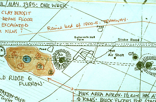
Note "G5" on this map - probably another ground
collapse in support of this general account.